


С источником питания от постоянного тока 6 в-60 в 400W BLDC трехфазный бесщеточный двигатель контроллер PWM зал управления двигателем драйвер платы 12V 24V 48V
- Категории: Motor Controllers >>>
- Поставщик: Shenzhen,Qinda,Electronics,Co.,Ltd.

Поделиться:
Описание и отзывы
Характеристики
Product Description
Part number | Motor Controller |
Wechat/Tel | +8613534149774 |
Email/Skype | qindamodule@ 163.com |
1823232721 |
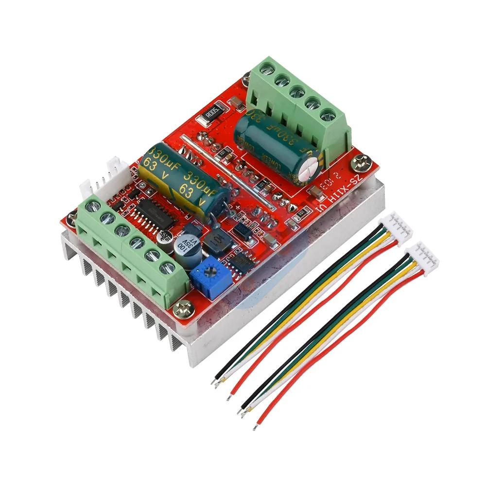
DC 6V-60V 400W BLDC Three-phase DC Brushless Motor Controller PWM Hall Motor Control Driver Board 12V 24V 48V Forward Reverse
Note: This drive is a DC three-phase brushless control board, which requires the motor to have a Hall to work normally
This drive is only suitable for DC brushless and Hall motors with an electrical angle of 120 degrees
Brand new upgrade BLDC wide voltage 6-60V high power 400W DC three-phase brushless with Hall controller, support PLC 0-5V analog control, support PWM to 0-5V control
Reminder: The baby is a self-developed product of the company. The circuit schematic diagram is not provided. Please understand that the anti-copy board part of the Guanjian IC has been polished. If you mind, don’t shoot
Special instructions for external signal input:
1. When the PWM signal is input from the main board terminal (need to remove the jumper cap on the board), it is also converted to a 0-5V signal and then enters the main control. Therefore, the amplitude and frequency are also required. The external signal source gives the PWM signal first. Set the 0 signal for a short time to make the master control reset to improve the stability of identifying the PWM signal.
2. When the analog quantity is input, you can use the on-board potentiometer to divide the voltage and adjust the speed, such as external 0-5V analog signal input from the terminal (need to remove the jumper cap on the board)
3. The forward and reverse rotation and brake are connected to 5V through a switch, which is high-level effective, and the external MCU can also give high-level signals. The front row of wiring terminals are weak current signals directly input to the MCU master control, and cannot be touched or touched To high voltage and strong current.Interface Description:
1. MA MB MC phase line output is connected to the motor
2. 5V GND The motherboard comes with a 5V power supply (can be externally powered, the current does not exceed 50MA)
3. VCC GND main power supply (external DC power supply)
4. SC speed pulse signal output (only the interface is reserved, no technical support)
5 direction control, forward and reverse control interface (high level is effective, external switch can be connected)
6. Speed control control speed control signal input (onboard integrated potentiometer for speed control can also be externally connected to 0-5V analog quantity, support PWM to 0-5 signal input for speed control)
7.Ha Hb Hc +5V GND Hall signal power input interface, generally the motor with Hall has 5 corresponding wires
Full chip technology, stable performance, with positive and negative brake function
Debugging instructions: Please turn on the test machine after reading and understanding, it is very important, very important, very important! ! !
After receiving the driver board, check whether the interface can correspond to the interface of your brushless motor.1. There are generally 5 Hall cables or interfaces on brushless motors, two of which are Hall power supply lines and three are Hall signal lines to distinguish, especially Hall power supply lines (Hall power supply lines generally use red and black lines , Or not, I don’t know how to find a way to find a motor manufacturer.) Don’t make a mistake. The three Hall signal lines are generally marked with abc. There are also three ports ha, Hb, Hc, and similar characters on the drive board, which are connected to each other.
2. There is on the motor There are also three phase line interfaces on the three thicker phase line drive boards. They are marked with MA MB MC and similar characters. They are also connected respectively. After confirmation, the main power supply can work normally. (If the interfaces are correctly mapped according to the labels, the power will not work, and the possibility of non-standard manufacturer labels or other reasons is not ruled out, please follow the following 3 interface definition is not clear to debug)
3. If you are not sure about the motor The definition of phase line and Hall line, then you can connect the three phase lines of the motor and the drive phase line interface arbitrarily, and at the same time connect the three signal lines of the Hall line to the Hall interface on the drive board (but two Hall power supply You must find a way to find out and connect the wires, remember!!!) Then, when the power is turned on for the first time, debug with low voltage and low current (if possible, use constant current power supply voltage to adjust to 7-12V and current 1-2A), and then By randomly changing the order of the three Hall wires (change any two between the three Hall signal wires of the motor and the drive Hall interface, and each time the power-on test is changed), the wiring is correct until it can run smoothly after power-on , When the wiring is incorrect, do not debug with high current or high voltage, otherwise there is a risk of damaging the drive board. After the three Hall signal wires are exchanged, if the corresponding connection is correct, the motor will run silky smoothly after the power is turned on, and the low speed will start and the torque will be large; If the three Hall signal wires are not connected in sequence, they generally have the following characteristics: 1. The motor does not start normally and there is no response or it only shakes when it starts.It is difficult to start with a slight jitter, and sometimes it needs to be manually turned.
4. The motor starts to jitter and is weak and there is a bath current. The high-power tube heats up.Humanized design, the interface uses the terminal, the standard heat sink, the integrated speed potentiometer on the board, it can be used when the hand is powered on, saving time and effort
Motherboard specifications:
Product name: 400W brushless DC motor driver with Hall effect
Model: ZS-X11H
Working voltage: 6-60V
Maximum current: rated 16A peak 20A
Maximum power: 400W
Overcurrent protection: Yes
Product size: length 63MM*width 45MM*height 31MM
Weight: about 73g
Precautions:
1. There is no fuse in the power supply circuit on the motherboard. Jianyi has added it himself. Reverse connection of the positive and negative poles of the power supply will cause permanent damage to some of the chips on the board (even 2 seconds will not work)
2. There is sampling over-current protection at the output of the motor during normal operation. Because the power and current of the module are very large, please do not artificially short-circuit when the module is not working normally. Once the short-circuit, the circuit may be burnt and the tube may burst. Please test with low current and low voltage. After ok, apply high current and high voltage. Because it is a bare board module, please pay attention to the insulation of the wiring head. It is strictly forbidden for strong voltage to touch the board parts.
3. Do not connect the motor that is obviously inconsistent with the drive module voltage, current, or power, to avoid inexplicable "nonsensical" damage


Click here for more details:
Company Information

Advantages

Packaging & Shipping

FAQ


Похожие товары


Новинки - Розница