XL6009 DC-DC Boost источника питания регулятор напряжения Повышающий Модуль Регулируемый выход 5V с цифровым дисплеем 4A светодиодный
- Категории: Voltage Regulators\/Stabilizers >>>
- Поставщик: Shenzhen,Zhicheng,Electronic,Technology,Co.,Ltd.
Поделиться:
Описание и отзывы
Характеристики

Company Profile

Specification

Type | Voltage Regulator Step-up Module |

Introduction:
Auto start voltage will be pulled down to 7V less or smaller engine
at high speed when the voltage up to 15V or higher. For 12V
electrical work hard at work, this automatic buck module solves this
problem, regardless of the input voltage is 5V or 12V or 32V, the
output can be stabilized at 12V.
Wide input voltage 5V-32V.
Wide Output Voltage 1.25V-35V (with automatic buck, scope of
work, any voltage inputs can be arbitrarily regulated voltage output);
Built- 4Aefficient MOSFET switches enable efficiency up to 94%;
(LM2577 current is 3A)
high switching frequency of 400KHz, the ripple is smaller and
smaller . (LM2577 frequency only 50KHz)
Application:
Car regulator, solar photovoltaic, wind power and other application
of voltage instbility.
Technical parameters:
. Model Specification: Automatic Buck module
. Module Properties: Non- isolated boost (BOOST)
Rectification: Non- Synchronous Rectification
. Input Range: 3.8V-32V
. Output Range: 1.25V-35V
. Input Current: 3A (max), no-load 18mA (5V input , 8V output,
no-load is less than 18mA. Higher the voltage, the greater the loadcurrent.)
. Conversion efficiency: <94% (greater the pressure, the lower theefficiency)
. Switching frequency: 400KHz
. Output Ripple: 50mV (the higher the voltage, the greater thecurrent, the greater the ripple)
. Load Regulation: +0.5%
●Voltage Regulation: +0.5%
. Operating Temperature: -40°C-+ 85°C
. Dimensions: 43.4mm*21.1mm*13.5mm (L *W*H)


Features:
. With voltmeter display, voltmeter error is +0.1V, range is 5~ 35V.
(Note: the input voltage is lower than 4.5V, the onboard voltmeterdoes not work and does not display)
Large volume 5*5 touch the button to switch between measuringinput or output voltage, and an indicator light shows which terminal voltage is being measured. By default, the digital tube displays the input voltage and the input indicator IN is on. When the button is touched, the digital tube displays the output voltage and the output indicator OUT is on. And keep the last setting, even after power off.
●The voltmeter can be turned off. Press and hold the switch for more than 1 second and less than 4 seconds. After the voltmeter is turned off, just press the switch briefly to turn on the voltmeter. The input and output voltage measurement error calibration function, long press the switch for more than 4 seconds, and enter the voltage measurement error calibration function after releasing the hand. At this time, the IN light is on (calibrating the input terminal), and the digital tube flashes to display a more positive value (factory parameter is 0.0). At this time, you can change this value by pressing the button shortly (the value range is -0.5~ 0.5, the unit is V). A positive number indicates upward calibration, and a negative number indicates downward calibration. After adjusting the calibration value of the input terminal, press and hold the button for more than 2 seconds, and enter the error calibration of the output terminal after releasing. At this time, the OUT light is on (calibrating the output terminal), and the calibration value of the output terminal is displayed. The adjustment method is the same as that of the input terminal. After the calibration value at the
output end, press and hold the button for more than 2 seconds, and save the set value and return to the normal display voltage after letting go, the set correction value will take effect immediately and will not be lost after power failure. (With this function, you can meet your higher accuracy requirements) With terminal block, it is convenient to use without soldering iron, and the welding wire connection point is reserved.(The input voltage must be more than 1v higher than the voltage to be output) The maximum output current can be as high as 3A. It is recommended that the working current be about 2A. Using an internal oscillation frequency of 400KHz, which belongs to the second-generation switching voltage regulator, with low power consumption and high efficiency.
Instructions:
. The input and output voltage measurement error is more accurate: press and hold the switch for more than 4 seconds, and the voltage measurement error comparison function is entered after releasing the hand. At this time, the IN light is on (calibrating the input end), and the digital tube flashes to display a more positive value (the factory parameter is 0.0), At this moment, press this button to change this value (the value range is -0.5~0.5, the unit is V), positive number means upward calibration, negative number means downward calibration. After adjusting the calibration value of the input terminal, press and hold the button for more than 2 seconds, and enter the error calibration of the output terminal after
releasing. At this time, the OUT light is on. (calibrating the output terminal), and the calibration value of the output terminal is displayed. The adjustment method is the same as that of the input terminal. After the calibration value at the output end, press and hold the button for more than 2 seconds, and save the set value and return to the normal display voltage after letting go, the set correction value will take effect immediately and will not be lost after power failure. (With this function, you can meet your higher accuracy requirements) Turn off the voltmeter: long press the switch for more than 1
second and less than 4 seconds, you can turn it off with a loose hand. After the voltmeter is turned off, just press the switch briefly to turn on the voltmeter.
Precautions:
. It is recommended to use a heat sink to enhance heat dissipation
when the power is used above 20W;
●Some customers report that the module output voltage cannot
be adjusted and is always equal to the input voltage. When you
encounter this problem, please turn the potentiometer counter
clock wise more than 10 times before using the module to adjust
the voltage normally.
Applications:
This module can be applied in the boost field where the output
voltage is higher than the input voltage, such as batteries, power
transformers, DIY adjustable regulated power supplies, 24V car
laptop power supplies, industrial equipment voltage reduction, 9 to
12V,12Vto18V18Vto24Vandsoon.


Our Advantages

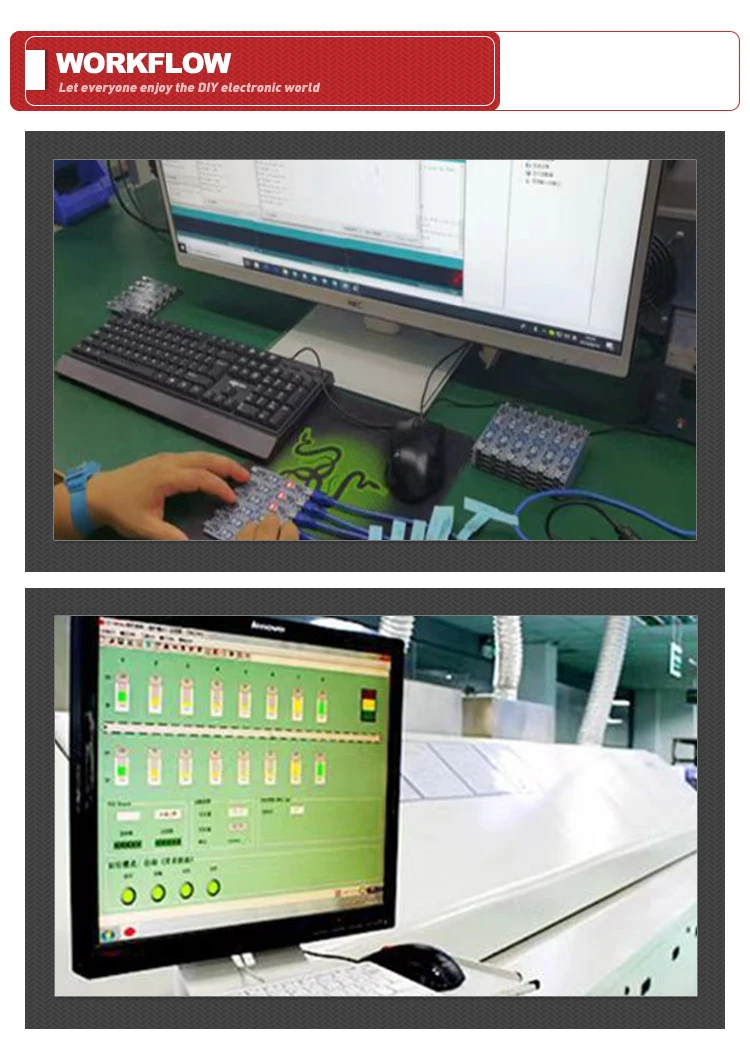
Workflow
Product packaging

FAQ
Q: What company do we belong to?
A: We are a manufacturer and a trader.
Q: How long is our delivery time?
A: This depends on the quantity of the goods you ordered, we have stock, usually 15-20 days
delivery time.
Q: How to order?
A: Please mail your order or request to us, and tell us the following information: shipping details, including company name, address, person, phone number, quantity.
Q: How many discounts are available for ordering products?
A: As long as you provide us with your demand, we will give you the best price.
Q: What can you buy from us?
A: Integrated circuit, Electronic components, Module, IC , The power supply Module, 3D printers
Parts, Raspberry Pi Accessories, Smart Robot, Audio accessories.
Похожие товары
Автоматический стабилизатор напряжения SVC 5 ква
US $80.00-$100.00
Автоматическое регулирование напряжения 5000 Вт
US $150.00-$392.00
AVS защита мощности 5А защита для телевизора
US $2.50-$3.50


