Датчик дифференциального давления от китайского производителя с
- Категории: Pressure Measuring Instruments >>>
- Поставщик: Yantai,Auto,Instrument,Making,Co.,Ltd.

Поделиться:
Описание и отзывы
Характеристики

Product Specification

Introduction
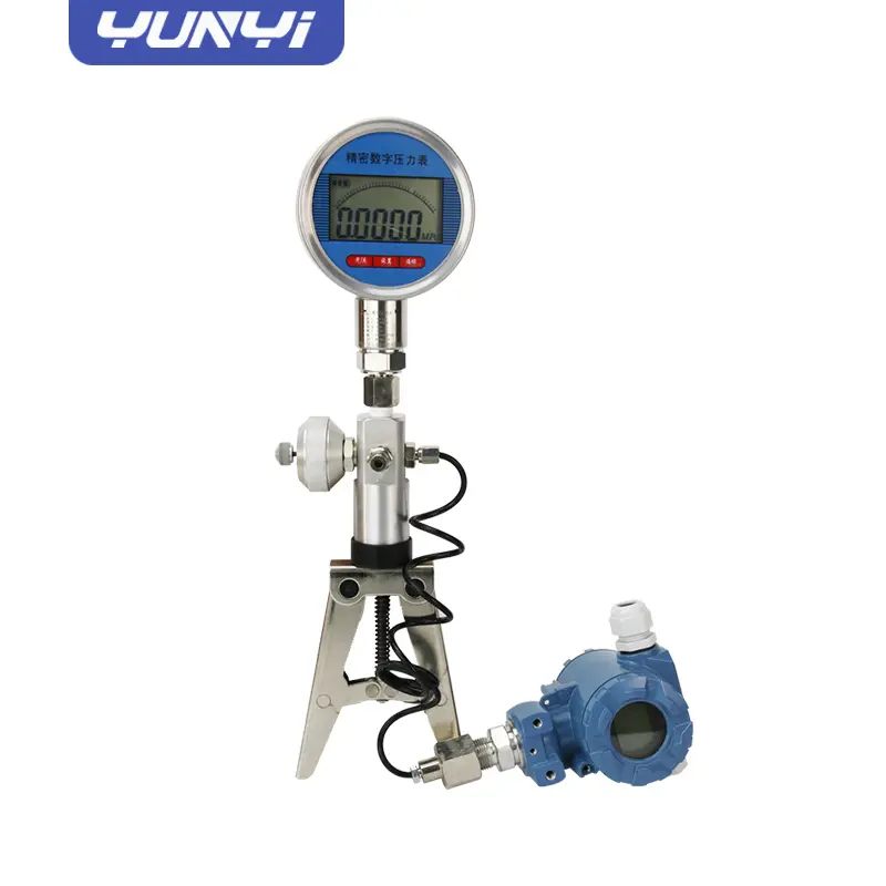
The (differential) pressure transmitter is suitable to measure liquid, gas, or steam flow as well as liquid level, density and pressure. Outputs a 4~20mADC signal corresponding to the measured differential pressure. Its highly accurate and stable sensor can also measure the static pressure which can be shown on the integral indicator or remotely monitored via HART communications. Other key features include quick response, remote set-up using communications, self-diagnostics and optional status output for pressure high/low alarm.
Features
1. Process Fluid: Liquid, Gas, Vapor
2. Applicat ion: Differential Pressure, Gauge Pressure,Absolute Pressure
3. Working Temperature: -25 to +95C
4. Current Output: 4 - 20 mA 2 wires Har t Protocol
5. Power Supply: 24VDC
6. Ambient Temperature: -25 to +240C
7. Process connections: 1/4 - 18 NPT or 1/2 - 14 NPT
8. Electrical Connections: 1/2”NPT or M20*1.5
9. Enclosure:IP65
10.Intrinsically Safe: Exia II C T6
11.Explosion proof: Exd II B T5
Product Details

Product Order Sheet
Name | Specification code | Description | ||||
AT3051GP AT3051DP | Pressure Transmitter Differential Pressure Transmitter | |||||
Measurement Range | 2 | 0-0.1~1.5 Kpa | ||||
Measurement Range | 3 | 0~7.5 Kpa | ||||
4 | 0~37.4 Kpa | |||||
5 | 0~186.8 Kpa | |||||
6 | 0~690 Kpa | |||||
7 | 0~2068 Kpa | |||||
8 | 0~6890 Kpa | |||||
9 | 0~20680 Kpa | |||||
Output | J | 4-20mA, HART Protocol, Linear output | ||||
Output Signal | S | 4-20mA, HART Protocol, Square root output(Range≥5kpa) | ||||
Diaphragm Material / Fill Fluid | 2 | Stainless Steel 316L Silicone Oil | ||||
3 | Hastelloy C(range >3Kpa) Silicone Oi | |||||
A | Stainless Steel 316L Fluorine oil | |||||
Drain hole | B | Back of process flange or none | ||||
U | Process flange side upper | |||||
L | Process flange side lower | |||||
Wetted O-ring Material | 7 | Buna-N (NBR) | ||||
Wetted O-ring Material | 6 | Viton (FKM) (Temperature ≥-20℃) | ||||
5 | Low Temperature Viton (FKM-GFLT) | |||||
Process Connection | H | 1/4'' NPT F | ||||
Maximum Pressure Limit | 1 | 14 Mpa( 4Mpa for range 2) | ||||
3 | 25 Mpa | |||||
5 | 32 Mpa | |||||
Cable Entry | 1 | M20*1.5 | ||||
Mounting Bracket | B00 | None | ||||
Mounting Bracket | B01 | Tube-type Curved Bracket (carbon steel) | ||||
B02 | Wall mounting bracket (carbon steel) | |||||
B03 | Tube-type Flat Bracket (carbon steel) | |||||
B04 | Tube-type Curved Bracket (stainless steel) | |||||
B05 | Wall mounting bracket (stainless steel) | |||||
B06 | Tube-type Flat Bracket (stainless steel) | |||||
Optional | M3 | LCD display | ||||
Process Flange | d | Intrinsically safe type, Flameproof (Exd IIC T4~T6) | ||||
i | Intrinsically safe (Exia IIC T4~T6) | |||||
D1 | Stainless steel drain valve or screw (2pcs) | |||||
Flange Joint | C1 | 1/2'' NPT female waist flange (2sets) | ||||
C12 | 1/2'' NPT-M20*1.5-Φ14 pressure pipe (2sets) | |||||
C2 | M20*1.5 male thread T joint (2sets) | |||||
C21 | M20*1.5 T joint -Φ14 pressure pipe (2sets) | |||||
K1 | Degreasing treatment | |||||

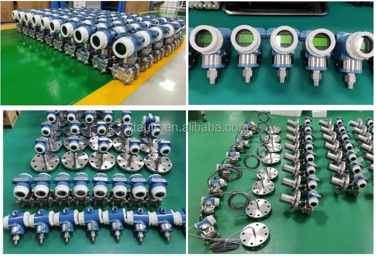
Production Line


Applications


Company Profile


Yantai Auto Instrument Making Co., Ltd
Yantai Auto Instrument Making Co., Ltd has advanced production equipment and high-precision import calibration equipment. It is a high-tech enterprise integrating with product design, research and development, production and sales.Our products are widely used in enviroment protection, power, petrochemical, metallurgy, electric power, pharmaceutical, food and other industries. Products are exported to more than 60 countries and regions such as the United States, Germany, Russia, India, Vietnam, South Korea and Pakistan etc. We offer maintenance services for other brands like Rosemount, Yokogawa, Honeywell.
Certifications

Contact us

FAQ
Q: Can you make customized products?
A: Yes, customized is accept, please contact us for specific requirements.
Q: How to track my Order?
A: After shipped, we will email you the tracking number. You can check the shipping status of your order on the website.
Q: How about warranty ?
A: Warranty: 12 months.
Q: How about after-sales service?
A : We are 24 hours online, if you have any problem, please contact us directly.
Q: Any discount?
A : For bulk purchase or distribution agents, we will apply the best price for you. If we have any promotions, we will post in
store and send you an email to inform you.
A : For bulk purchase or distribution agents, we will apply the best price for you. If we have any promotions, we will post in
store and send you an email to inform you.
Похожие товары
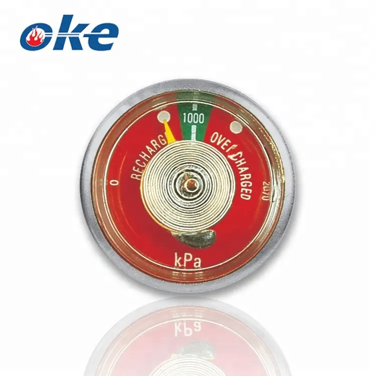
Огнетушитель Трубка Бурдона манометр
US $0.60-$4.00


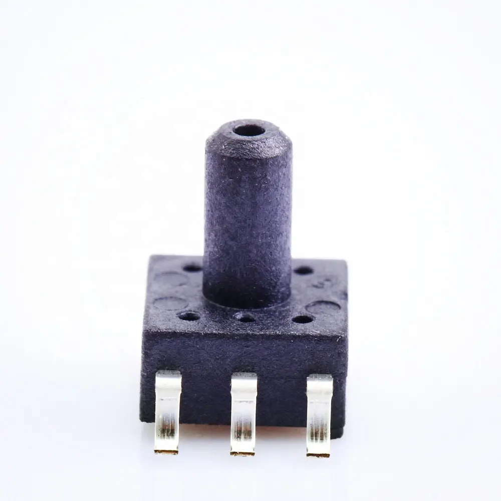

Датчик давления с дисплеем, умный преобразователь 4-20mA Hart RS485
US $135.00-$150.00
Новинки - Розница