Автомобильный Внешний аварийный стартер Changfa 4S 12 в BMS lifepo4 35A/50A мгновенный ток 800A/1200A
- Категории: PCB & PCBA >>>
- Поставщик: Huizhou,Changfa,Electronic,Technology,Co.,Ltd.

Поделиться:
Описание и отзывы
Характеристики
Video Description
Product Paramenters
Discharge current(MAX) | 35A | 50A | ||
Charging current | ≤15A | ≤30A | ||
The main circuit conducts the internal resistance | ≤3MΩ | ≤2MΩ | ||
Instant starting current | 800A | 1200A | ||
Overcharge protection | Overdischarge voltage protection | ||||
Detection voltage | 3.65±0.025V | Detection voltage | 2.35±0.1V | ||
Detection delay | 1000±500MS | Detection delay | 1000±500MS | ||
Release voltage | 3.45±0.05V | Release voltage | 2.7±0.1V | ||
Balance voltage | Discharge overcurrent protection | ||||
Detection voltage | 3.5±0.025V | Detection voltage | / | ||
Detection delay | 100±50MS | Detection delay | / | ||
balance current | 35±5MA | Overcurrent protection | / | ||
Short circuit protection | Temperature protection | ||||
Trigger condition | / | Charging temperature | customize | ||
Detection delay | / | Discharge temperature | customize | ||
Release condition | / | Release condition | Restore within operating temperature | ||
Consumable electricity | ||||||
Working power consumption | ≤40UA | |||||
Hibernation over discharge consumes power | ≤10UA | |||||
Operating temperature range | -20°C+80°C | |||||
Product Description
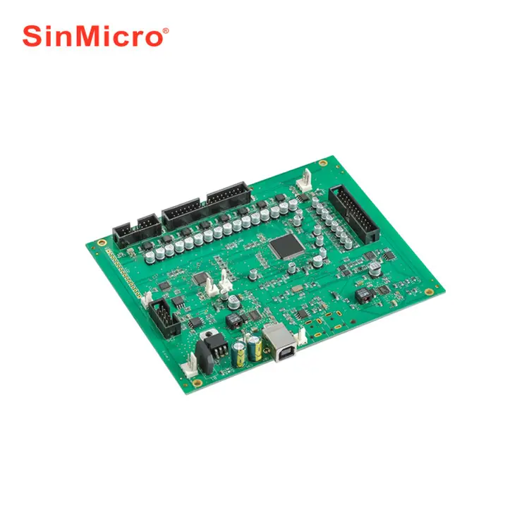
CF-8S80A-A
CF-8S80A-A is designed by Huizhou Changfa Electronic Technology Co., LTD., specially designed for outdoor car emergency power supply 3-4 series ternary lithium/lithium iron phosphate battery pack/outdoor power supply products protection plate scheme. Suitable for lithium ion, lithium polymer, lithium iron phosphate and other different chemical properties of lithium batteries, protection plate bearing capacity, the maximum continuous discharge current up to 35A/50A, instant current up to 800A/1200A.
(1) 3-4 batteries in series protection
(2) charge and discharge protection function
(3) Temperature control protection (customizable, consult customer service)
(4) B-C- output thick line (customizable, consult customer service)
(5) real standard current
(6) If you need other string number or current (contact customer service consultation and customization)
Installation Instructions
Protection board wiring diagram
The wiring method of different manufacturers is different. Do not insert protection plate in the welding wiring
If only one string is used as an example, the same analogy can be used to connect the protection board with other string numbers

*lmportant note: Different manufacturers different connection, please buy the supporting line of the protection board, do not useother do not belong to the supporting line!! Due to the use of parts do not belong to the usual wiring, if there is a problem,will not accept return and replacement! *

Step 1: Connect cables to the protection board
First connect the B- and C- wires on the protection plate (the split-plate needs to be connected to P, and the same plate C- needs to be charged and discharged, and the wires must be thick). The B- wires should be welded to the total negative electrode B- of the battery, and then connect the bar wires (before connecting the bar wires, be sure to pull the bar wires from the plate).

Step 2: Acquisition voltage line welding
Start wiring from the black thin wire at the far right of the row (connected to the total negative terminal of battery B), the second row of wires from the black thin wire to the left of the first thin wire connected to the first series of positive battery (the first battery of the total negative terminal), the third row of wires connected to the second series of positive battery, the fourth row of wires connected to the third series of positive battery... . ... In order from right to left, and so on, until the final series of total positive B+.

Step 3: Measure the output voltage
Finally, measure whether the total voltage of the battery and the output voltage of the protection board are equal, equal protection board is working normally.
Factory manufacturing

FAQ
1. What type of charger should I choose?
Lithium battery must choose specific charger, do not use Charger for Leadacid battery, for leadacid charger may have MOS with high pressure breakdown protection, which will not protect of BMS over charge. Life Po4 battery charger voltage=battery string No.X3.6V, while Li-ion battery charger voltage=Battery string No.X4.2V.
2.The relationship between Battery capacity and BMS current?
There is no direct relationship between Battery capacity and BMS current, big capacity doesn`t mean a big battery, but rely on continue current, that is to say if your engine is powerful, your should choose high current of BMS, it is not relied on batterycapacity.
\t
3.Whether my BMS damaged?
If you want to judge if the BMS is damaged, please take the folowing steps, to test if each cell voltage is the same with
voltmeter? if the cell voltage difference is over 1.0V, the fault is displayed that it cannot run far, no power supply at the
start range, short charge time, all these issues are almost caused by battery cells, if BMS damaged is displyed as no charge, no discharge, no discharge while the battery has voltage..
4. What is the difference between integration and single-section cascading?
(Single-section cascading scheme)
Advantages: string number can be downward compatible, flexible use, the same port protection plate charging current value and discharge current value is consistent. (The current market use relatively widespread)
Disadvantages: The voltage sampling line is not protected, and the performance is not as stable as the integrated solution.
(Integration solution)
Advantages: high temperature, low temperature protection; Compared to the single cascaded performance is more stable with charge overcurrent protection.
Disadvantages: Single string number, unable to downward compatible with other string numbers; The charging current at the same port is lower than the discharging current.
5, what is the same mouth and mouth, what is the difference between the two?
For example, we use 13 strings of 48V15A guard plates.
The same port protection plate: The same port 15A means that your charging negative electrode and discharge negative electrode is connected to the same point on the protection plate (our C-), charging and discharging negative electrode share a common interface, so its charging current and discharge current are the same 15A.
Mouth protection plate: then the mouth is just the opposite, charging negative electrode (C-) and discharge negative electrode separate (P-), connected to the different points of the protection plate.
6. What is the balancing function?
The working principle and function is as follows: when one section of your battery voltage reaches (polymer 4.18V, iron 3.6V), the equalization of this section on the protection plate will automatically turn on the equalization. After the equalization is turned on, the equalization resistance on the protection plate will start discharging with a current of 35MA (when the equalization discharge is turned on, there will be a slight heat on the back of the protection plate. It's a normal reaction.)
Похожие товары


Новинки - Розница